Project documentation // R&D division
SKW-RD-003
ROUND — CNC Bed Mill
A compact epoxy-granite bed mill, so the plates, brackets and motor mounts for every other build get cut on our bench instead of bought.
- Designation
- SKW-RD-003
- Version
- 1.0
- Platform
- Epoxy granite · IKO TU50 · THK KR46 · Teknic ClearPath · grblHAL
- Status
- Drawn · parts in hand
01 · The Problem
Every build I do ends in the same place: plates, brackets, motor mounts. And every one of them gets cut somewhere else, at someone else’s price, on someone else’s schedule. STÁLHRÍÐ’s thirteen plates went out to a laser-cut service. The drones need frames. The motor-drive work needs heatsinks, enclosures and fixtures.
Outsourced, each revision is a new order and a shipping wait. Owned, a revision costs stock and an evening.
02 · The Solution
A stiff base, bought motion. Every precision moving part is purchased. Everything I fabricate is a plate, a pour or a tube.
- Base: a 25-inch round A36 plate on three levelling feet, under roughly 125 mm of epoxy granite (about 72 L) with studs cast in. On top sits a 24 × 30 in plate, Blanchard ground on both faces. That’s the datum.
- Motion: crossed IKO TU50 linear stages carry the work, with a second TU50 plus SSR15 rails on the upper axis. The spindle only moves in Z, on a THK KR46 actuator.
- Column: a 6 × 6 in steel tube, 700 mm tall, filled with epoxy granite, with a ground front plate. Through-bolted joints. No welds on any ground face.
- Drives: three Teknic ClearPath servos in step/direction, straight onto the NEMA 23 faces.
- Spindle: a 2.2 kW water-cooled ER20 spindle on a VFD.
- Control: grblHAL on a Teensy 4.1 over Ethernet, driven from gSender.
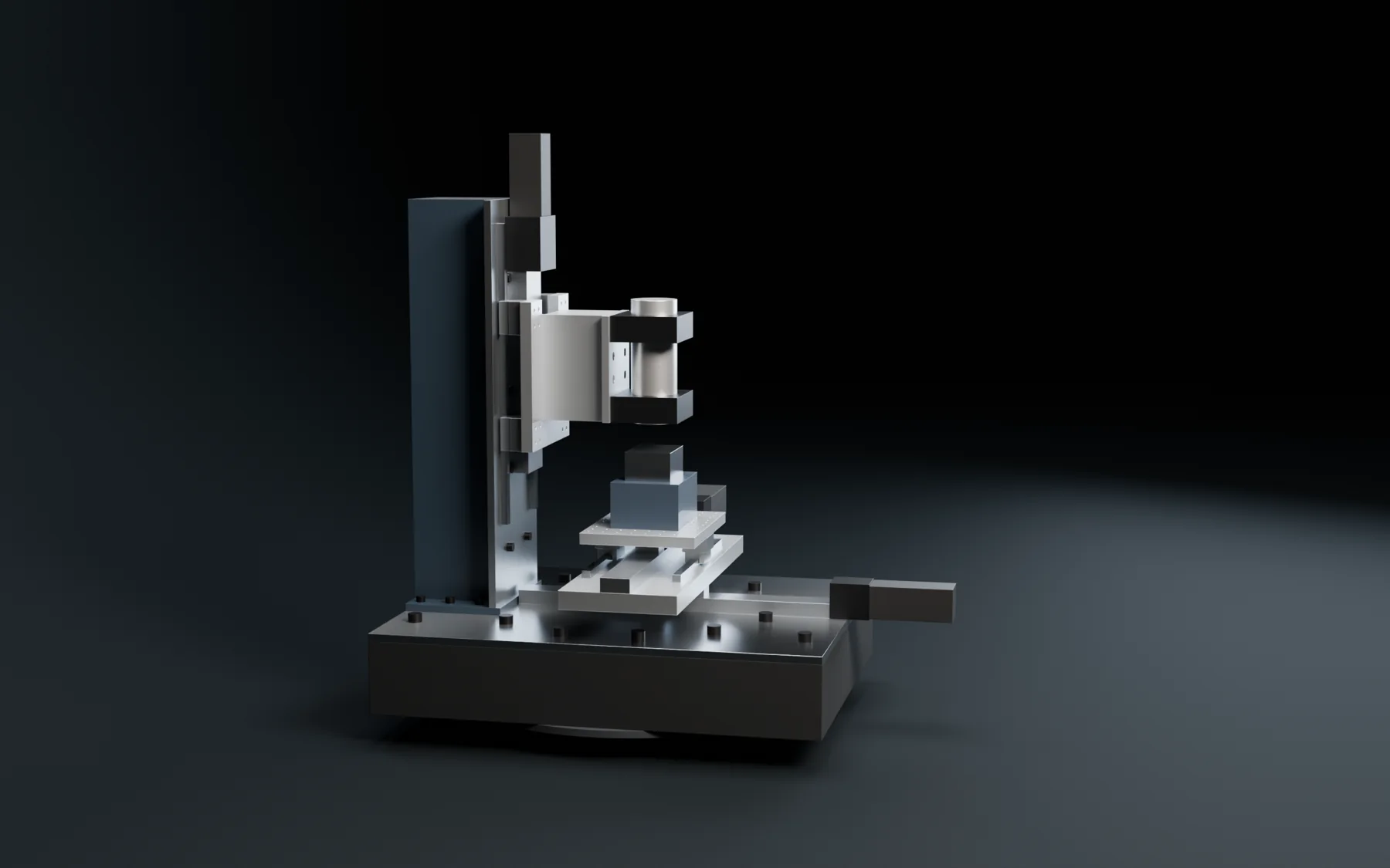 FIG 1 · ROUND from the side. The work moves on two crossed stages; the spindle only climbs.
03 · The Workflow — Calipers to Chips
- Measure. Caliper numbers go into one parameter file, tagged as measured.
- Model. FreeCAD builds the entire machine headless from Python and sweeps every axis through 21 poses looking for collisions.
- Draw. Every plate gets a true-scale drawing with a hole table, plus a STEP file.
- Test-fit. Full-scale PLA templates go on the real rails and blocks before any steel is cut.
- Pour and build.
One command regenerates all of it.
04 · The Hook — The Model Draws the Parts
Nobody models this machine by hand. One parameter file drives every plate, every hole table and every template, and every dimension in it carries a tag: measured, catalog, assumed, or open. Measured values never get changed. Open means ask; never guess.
A hole drawn from an unmeasured catalog figure stays red on the drawing until a caliper closes it. The cross plate has 32 holes, and 12 of them stay red until the rails under them are measured.
05 · What Saves Time
Change a number, not a drawing. The first 24 × 24 top plate left a linear stage hanging 121.6 mm off the front edge. One parameter changed it to 24 × 30, and the stage now sits 30.8 mm inside.
Find it on paper. Steel is expensive to get wrong and slow to fix. The sweeps caught:
- column bolt heads inside the saddle’s keep-out, so the bottom bolt row moved up 62 mm;
- the rear bearing blocks sweeping 6.9 mm over the column foot, so the foot shrank to 3.1 mm clear;
- a Z-axis clash the first check understated by 30.6 mm, now zero overlap across every pose.
An earlier bridge layout deflected about 0.9 mm under a 500 N cut load. ROUND calculates at 0.006 mm.
Plastic before steel. A wrong hole shows up as plastic instead of a scrapped plate.
06 · The Result
It’s drawn to the hole and bought to the motor. All of the motion hardware, servos, couplings, controller, spindle and sensors are on hand, and the controller is flashed and talking over Ethernet. The drawing set is done, with a handful of sheets still red until the last measurements close.
| Spec | Value |
|---|---|
| Travel | 283 × 283 × 245 mm (model) |
| Mass | ~350 kg (model) |
| Deflection @ 500 N | 0.006 mm (calculated) |
| Spindle | 2.2 kW · 24k rpm · ER20 |
Nothing has been cut yet. Until it cuts metal, every performance number here is a target.
07 · Future Work
- Close the last measurements, buy the ground top plate and column, and pour.
- First jobs: turret plates, drone mounts, motor-drive heatsinks, enclosures, PCB fixtures.
- A higher-voltage servo bus, servo fault feedback, spindle-load and vibration sensing.
- Running our own motor drives on one axis. That’s an idea, not a design yet.
- Then the big one: a 42-inch machine, already modelled and waiting.
Every build ends in plates and brackets. I want the machine that makes them on our bench.